To use this diagram, you must be competent and have had the appropriate training in accordance with the standards for central heating systems and boiler fault finding, including wiring for heating systems as outlined in Part L of the Building Regulations and other relevant codes of practice.


24V Zoned Valve Wiring Diagram: A Comprehensive Guide
Introduction to 24V Zoned Valves

Zoned heating systems using 24V zoned valves provide enhanced control over individual heating zones, offering energy efficiency and comfort. These systems are commonly used in residential and commercial settings to optimize heating based on specific needs.
Understanding the 24V Zoned Valve Setup
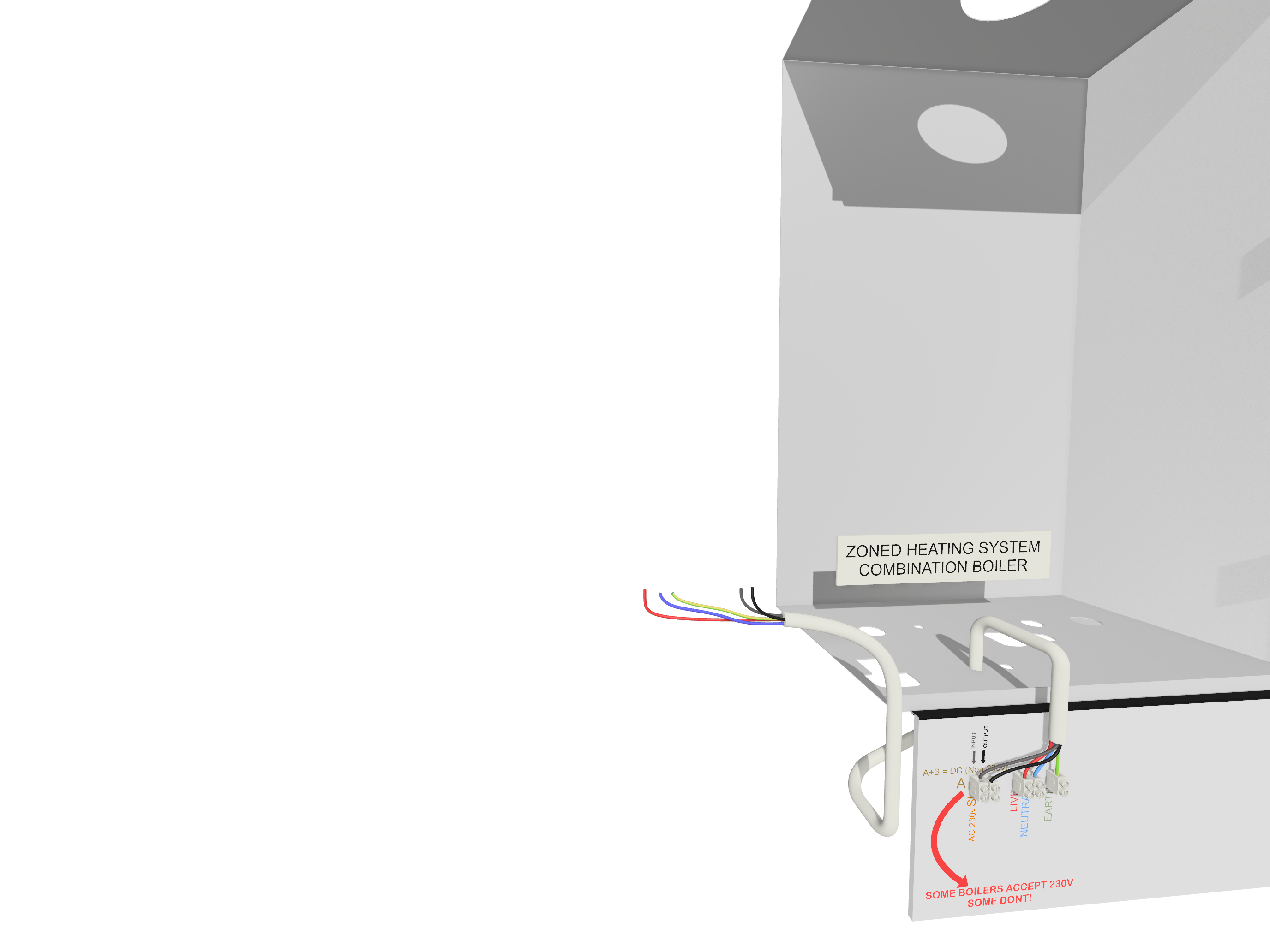
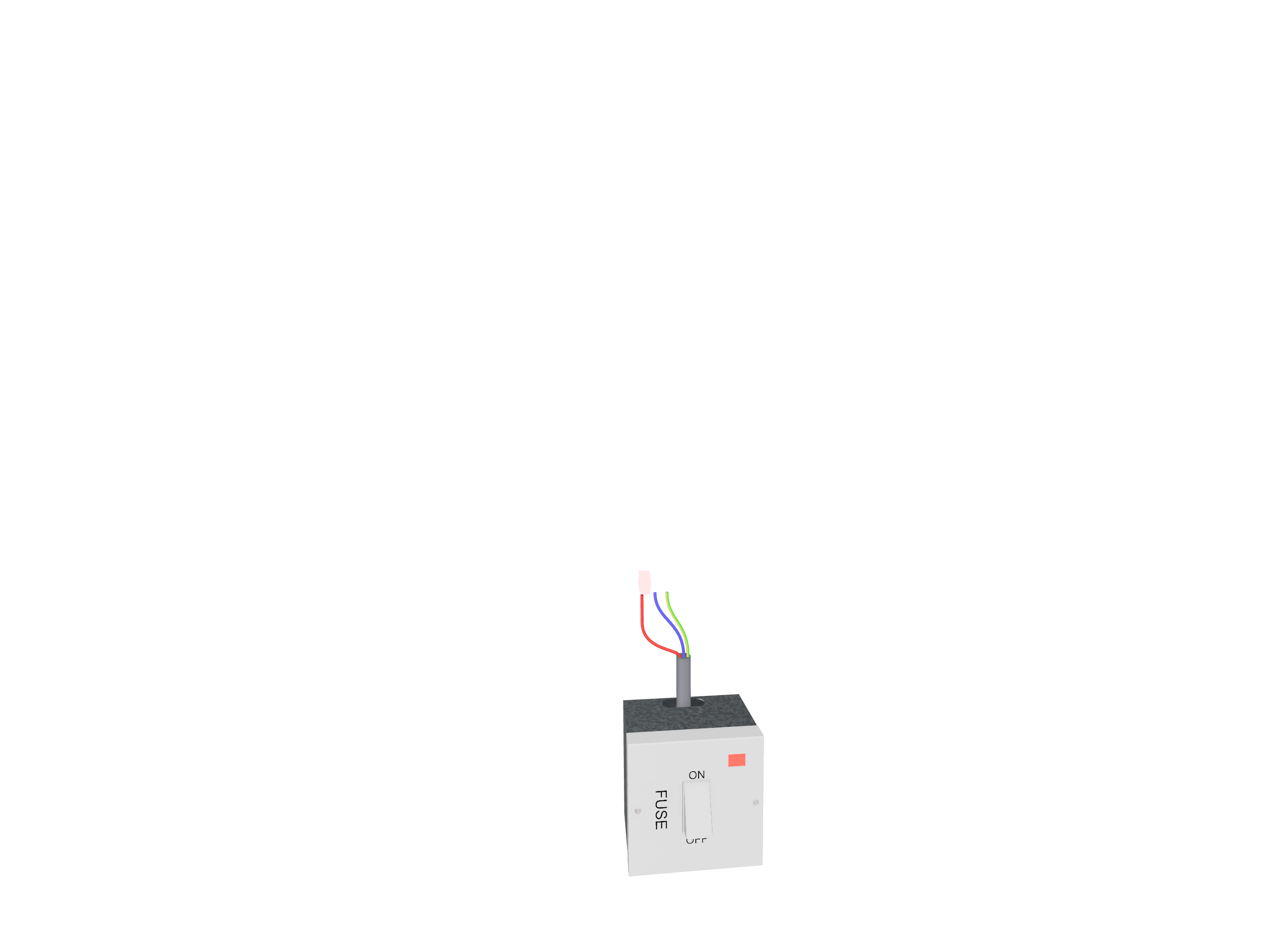
The primary reason for using 24V zone valves is due to the permanent grey wire that is typically connected within the system. This wire provides a controlled 24V circuit directly from the boiler, enabling efficient operation of the valves. However, it's important to note that some combination boilers may still utilize 230V circuits for valve control. Always check the boiler specifications to determine the appropriate wiring configuration.
Common Boilers That Support 24V Control
Many modern combination boilers provide built-in support for 24V zoned valve control. Typical models that use this low-voltage setup include:
- Worcester Bosch Greenstar
- Vaillant ecoTEC Plus
- Baxi 600 Series
- Ideal Vogue Max
- Viessmann Vitodens 100-W
How Does a 24V Zoned Valve System Work?
A 24V zoned heating system operates by using low-voltage control circuits to regulate the flow of hot water to different zones within a building. When a thermostat in a particular zone calls for heat, the corresponding valve opens, allowing heated water to flow to that area.
Components of a 24V Zoned Heating System
The key components of a 24V zoned valve system include:
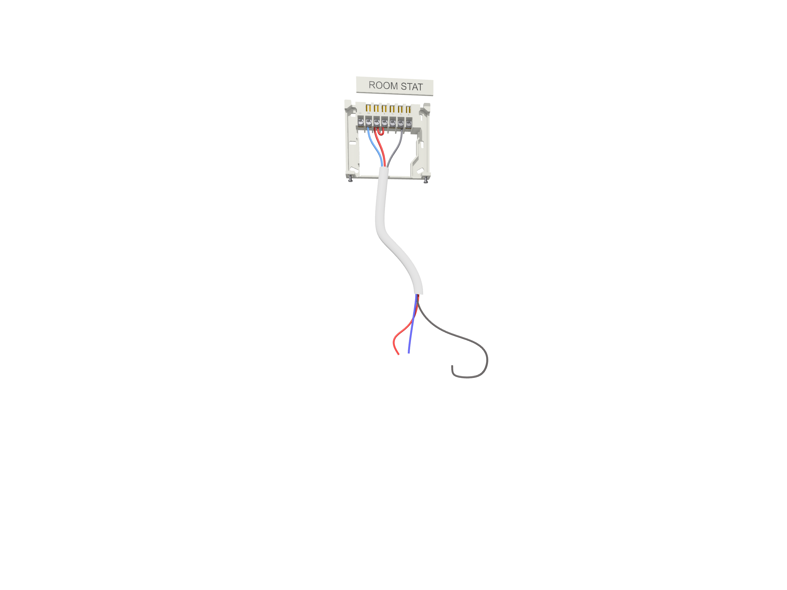
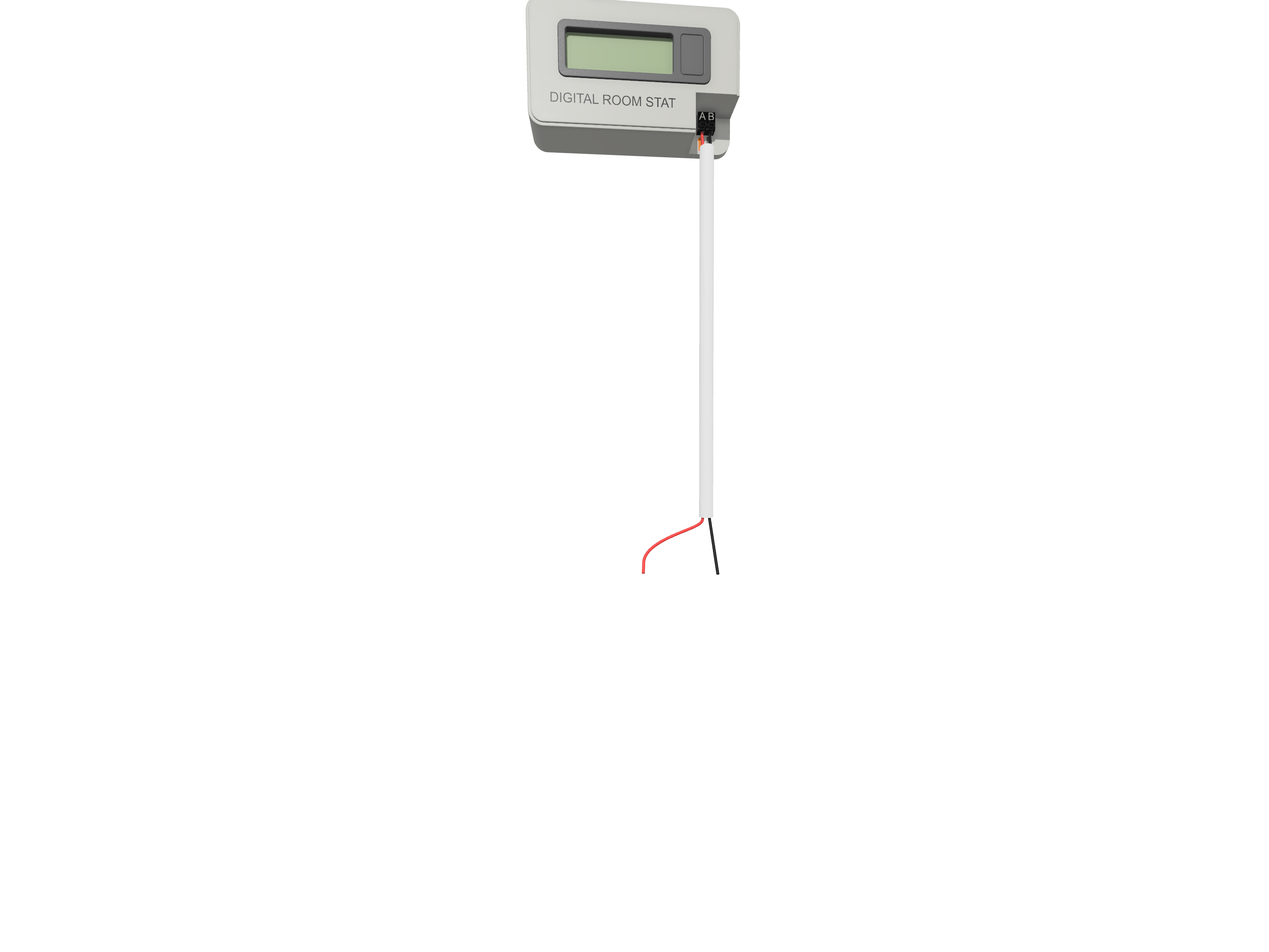
- Thermostats: Control the temperature for each heating zone.
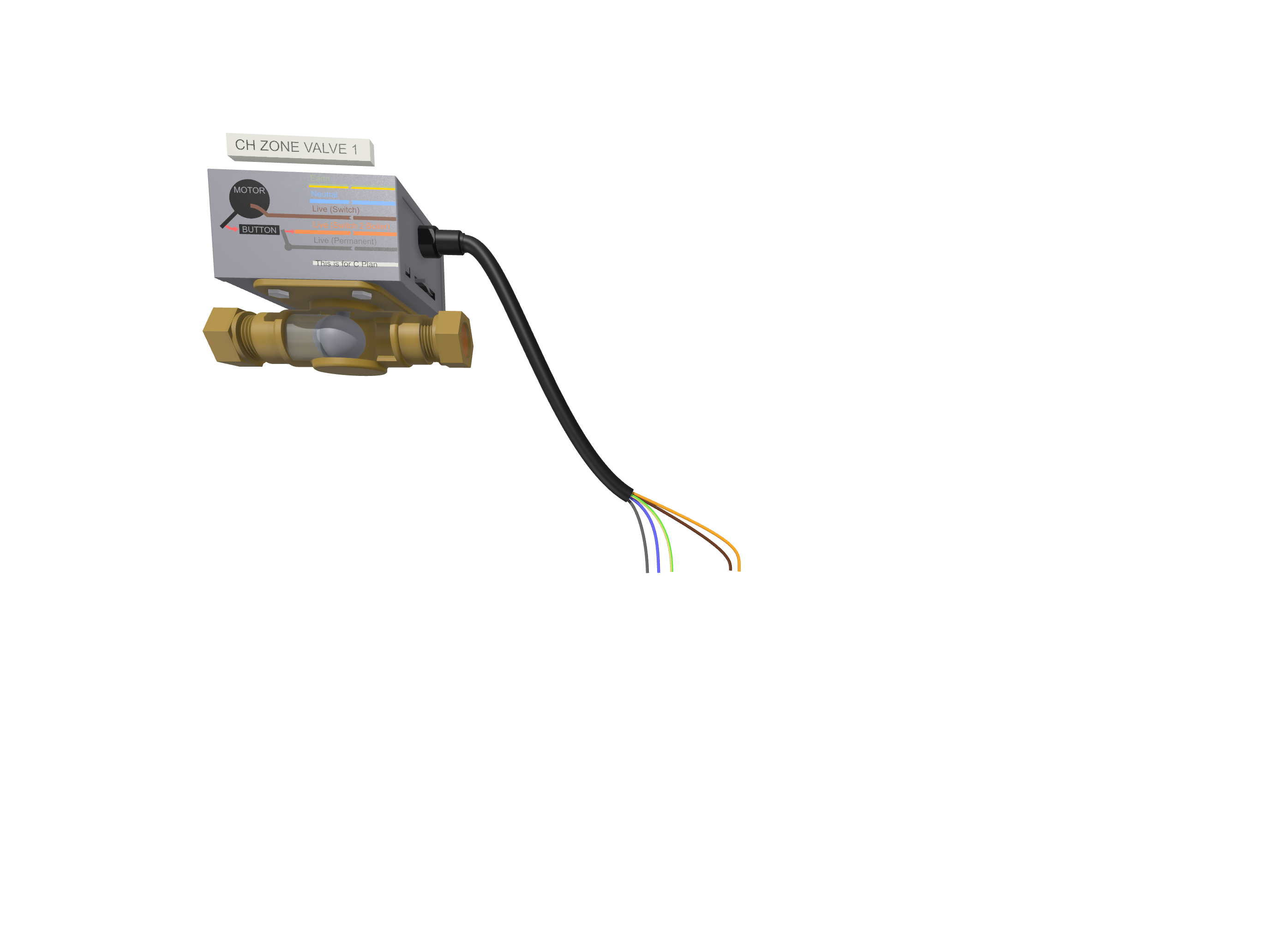
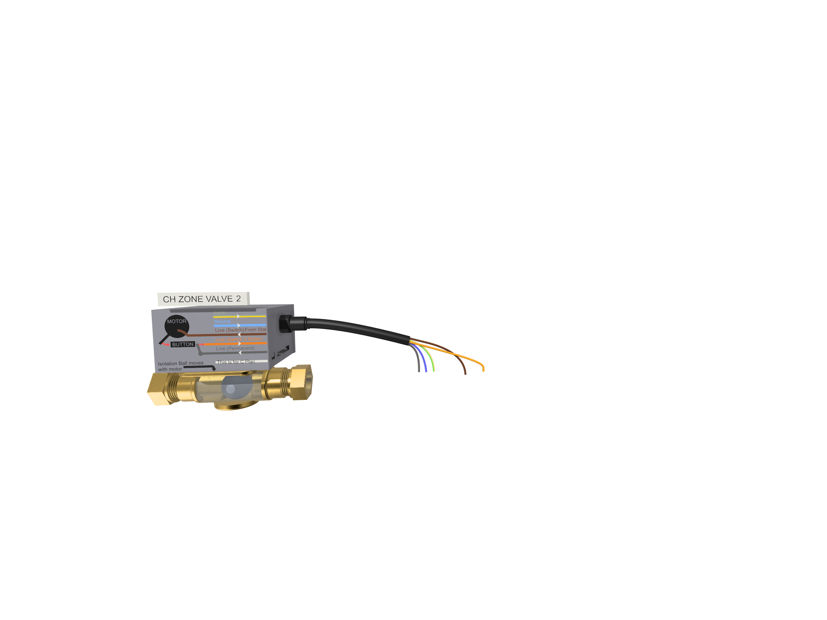
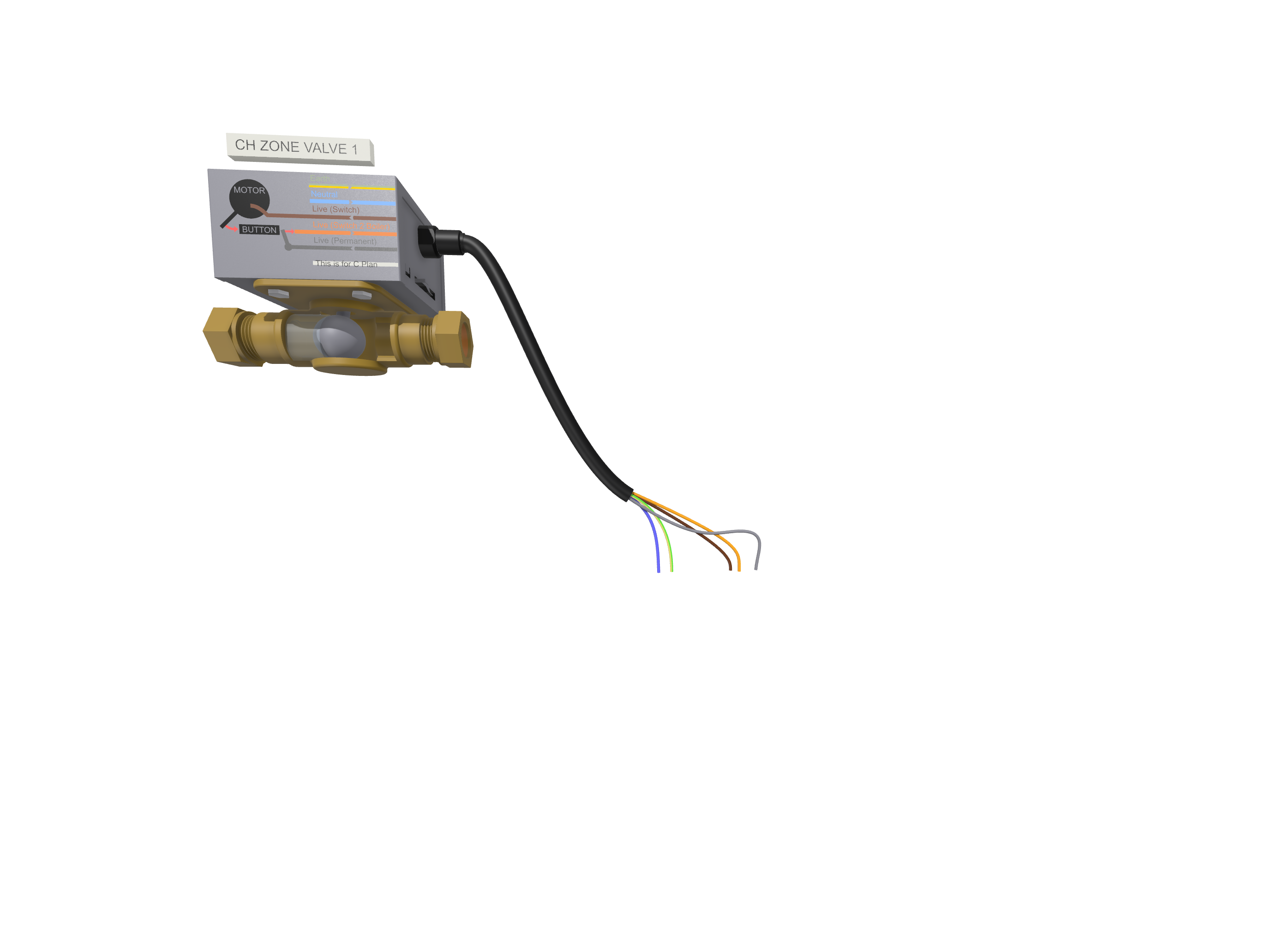
- 24V Zone Valves: Electrically operated valves that open and close to regulate water flow.
- Boiler: Provides the heated water to the system.
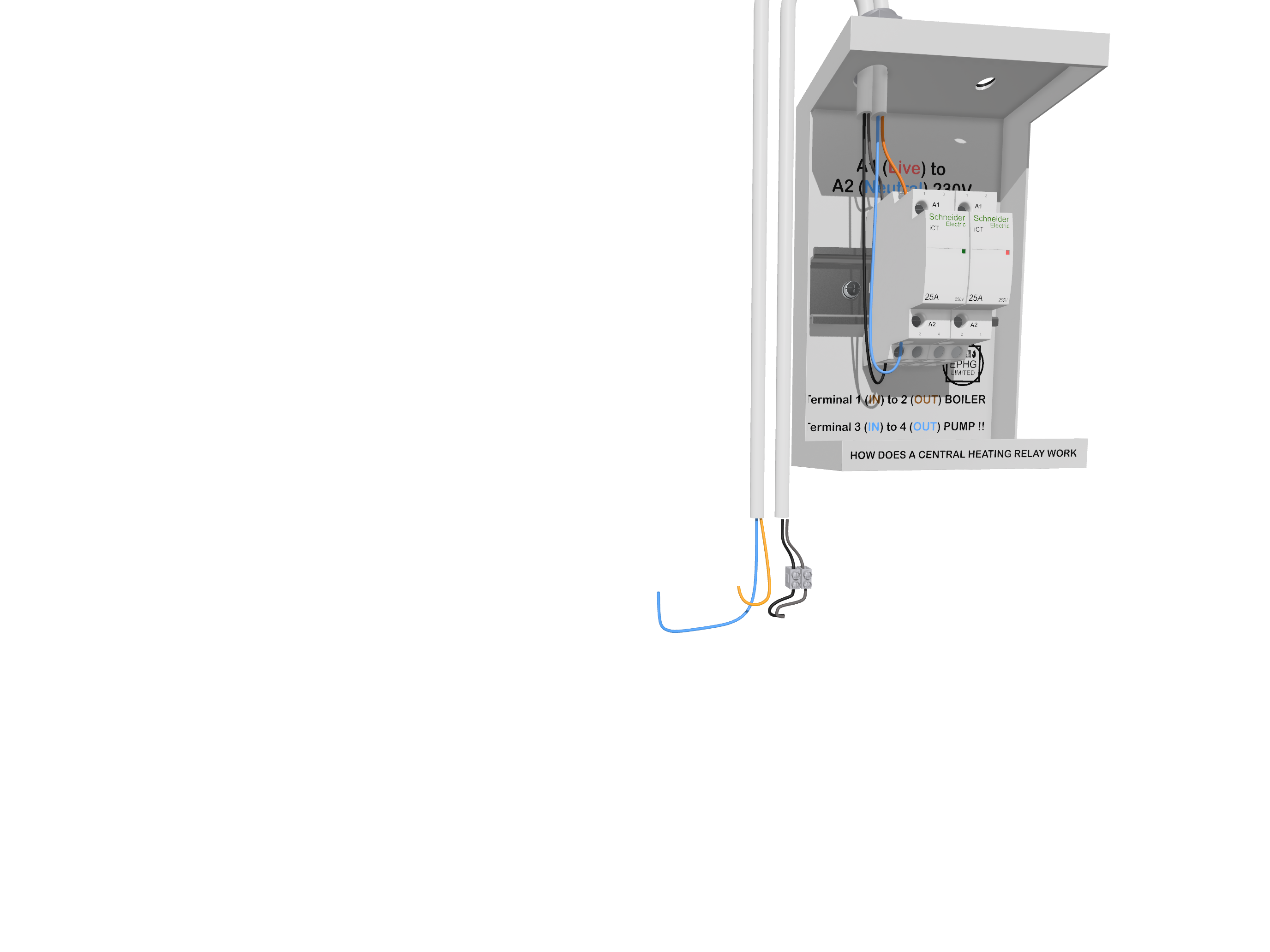
- Wiring Center: The hub for connecting all electrical components.
- Transformer: Converts 230V mains power to the required 24V for control circuits.
Step-by-Step 24V Wiring Guide
Follow these essential steps to wire a 24V zoned valve system correctly:
- Step 1: Identify the terminals on the zone valve (common, normally open, normally closed).
- Step 2: Connect the thermostat wires to the control board.
- Step 3: Wire the zone valve to the boiler’s control system.
- Step 4: Ensure proper transformer installation for 24V power supply.
- Step 5: Test the system by adjusting the thermostat and verifying valve operation.
Common Wiring Configurations
The most common wiring configurations for a 24V zoned heating system include:
- Two-Wire Configuration: Used for basic on/off control.
- Three-Wire Configuration: Allows more complex control with separate power and control wires.
- Four-Wire Configuration: Commonly used for systems with end switches to trigger the boiler.
Advantages of Using a 24V Zoned Heating System
Opting for a 24V system has several benefits, including:
- Energy Efficiency: Reduced power consumption compared to 230V systems.
- Improved Control: Individualized heating for different areas.
- Safety: Lower voltage operation reduces electrical hazards.
Troubleshooting 24V Zoned Valve Issues
If your 24V zoned valve system is not functioning correctly, consider the following troubleshooting steps:
- No Heat in a Zone: Check the thermostat settings and wiring connections.
- Valve Stuck Open: Inspect for mechanical obstructions or faulty wiring.
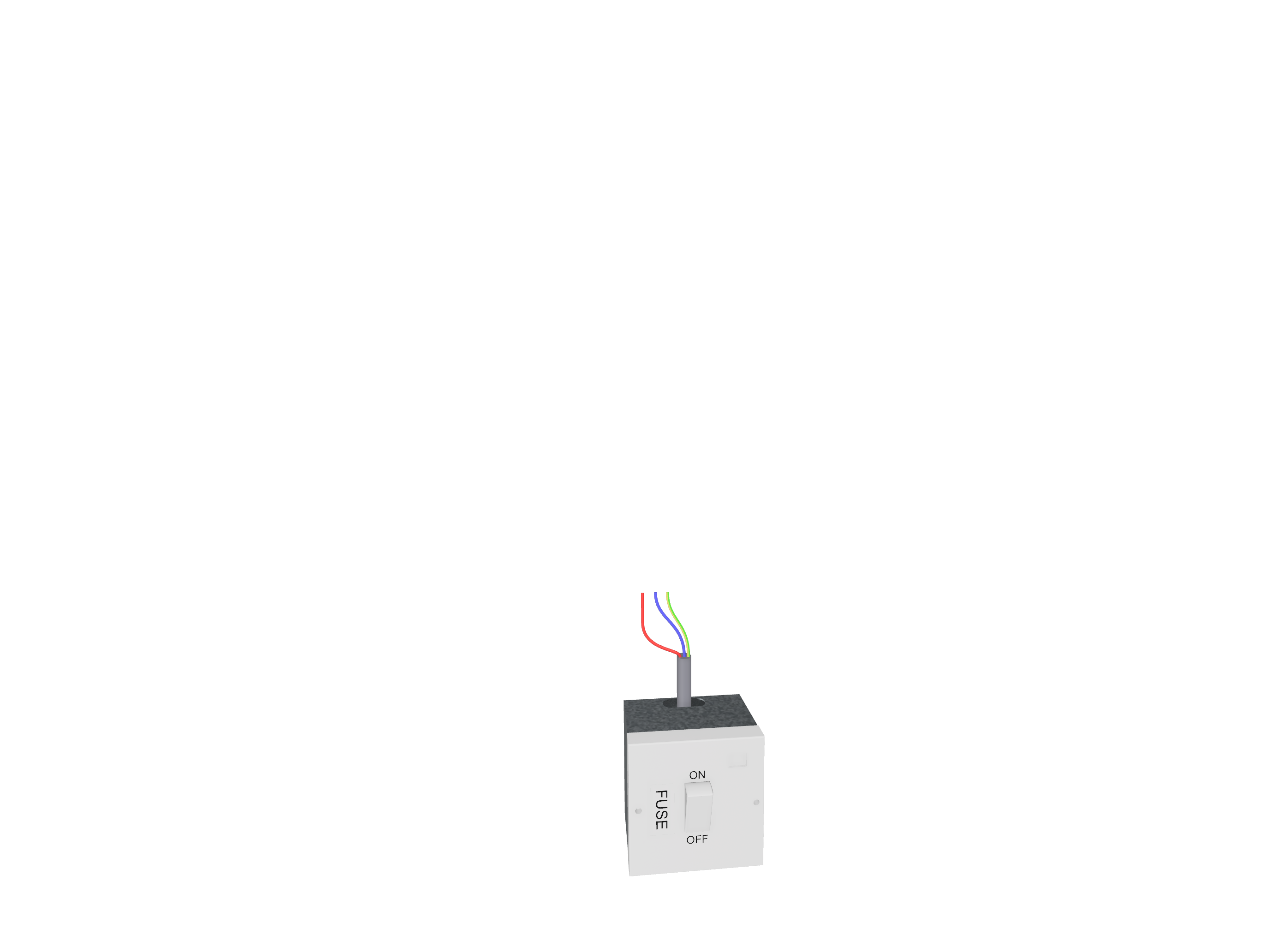
- System Not Responding: Verify transformer output and fuse status.
Related Zoned Valve Wiring Diagrams
Explore other related wiring diagrams for different voltage setups:
- 240V Zoned Valve Wiring Diagram – Learn how to wire a 240V system, which offers a higher voltage alternative to 24V setups.
- 24V/240V Combined Zoned Valve Wiring Diagram – Discover how to integrate both 24V and 240V using relays for better control.
Conclusion
A well-installed 24V zoned valve wiring system can significantly improve heating efficiency and comfort in a property. By following the correct wiring guidelines and troubleshooting techniques, you can ensure a reliable and effective heating solution. For more information on different central heating wiring plans, visit our Central Heating Wiring Plans page.