To use this diagram, you must be competent and have had the appropriate training in accordance with the standards for central heating systems and boiler fault finding, including wiring for heating systems as outlined in Part L of the Building Regulations and other relevant codes of practice.


240V Zoned Valve Wiring Diagram: Step-by-Step Guide
Introduction to 240V Zoned Valves

Zoned heating systems using 240V zoned valves are commonly found in domestic heating setups across the UK. These systems provide precise heating control by regulating the flow of hot water to different zones, ensuring energy efficiency and comfort.
Understanding the 240V Zoned Valve Setup
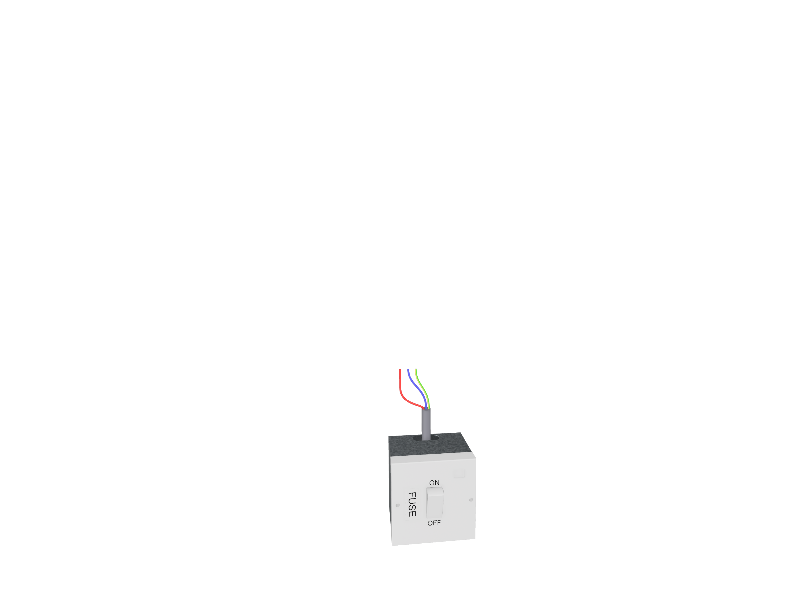
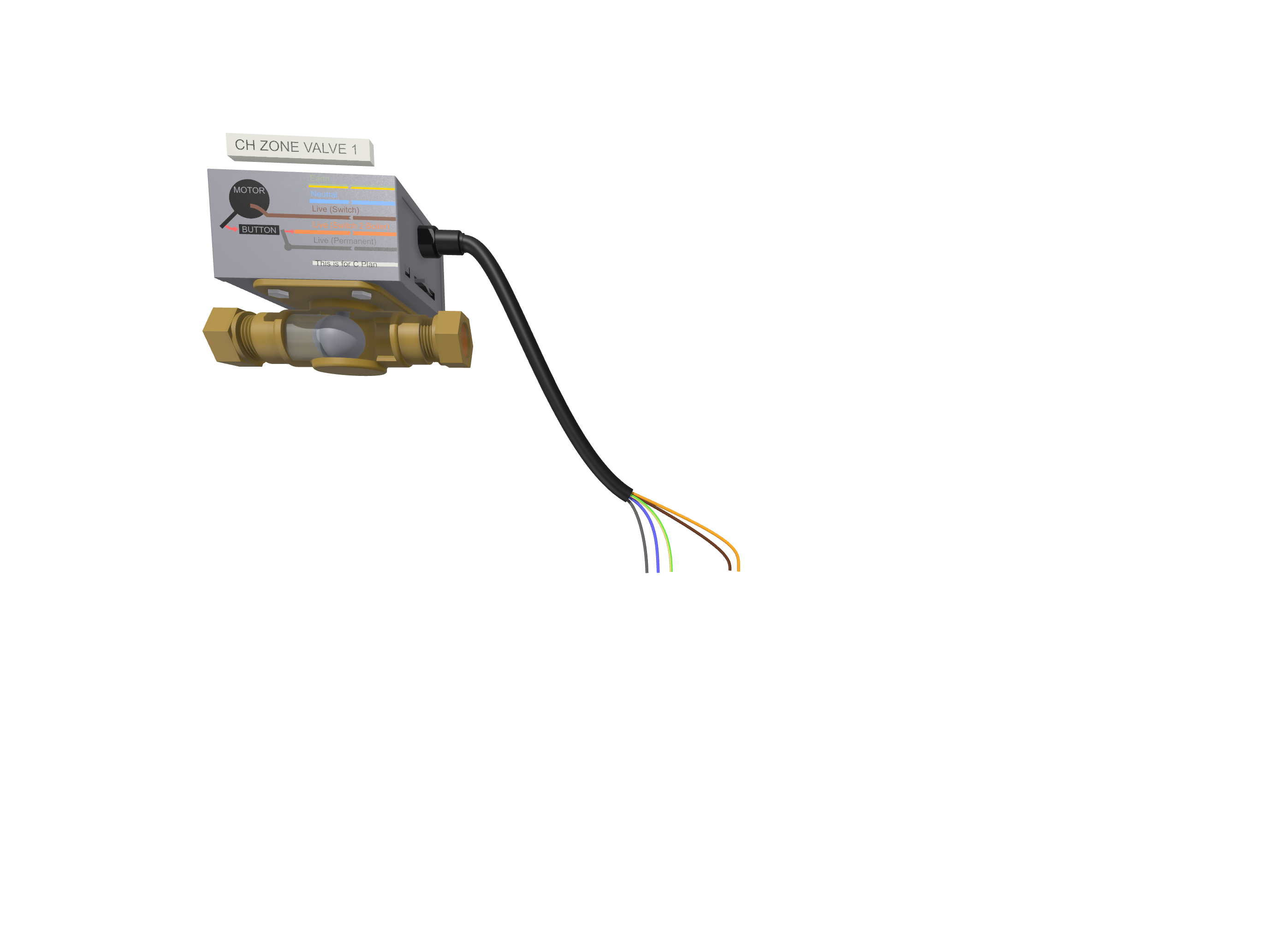
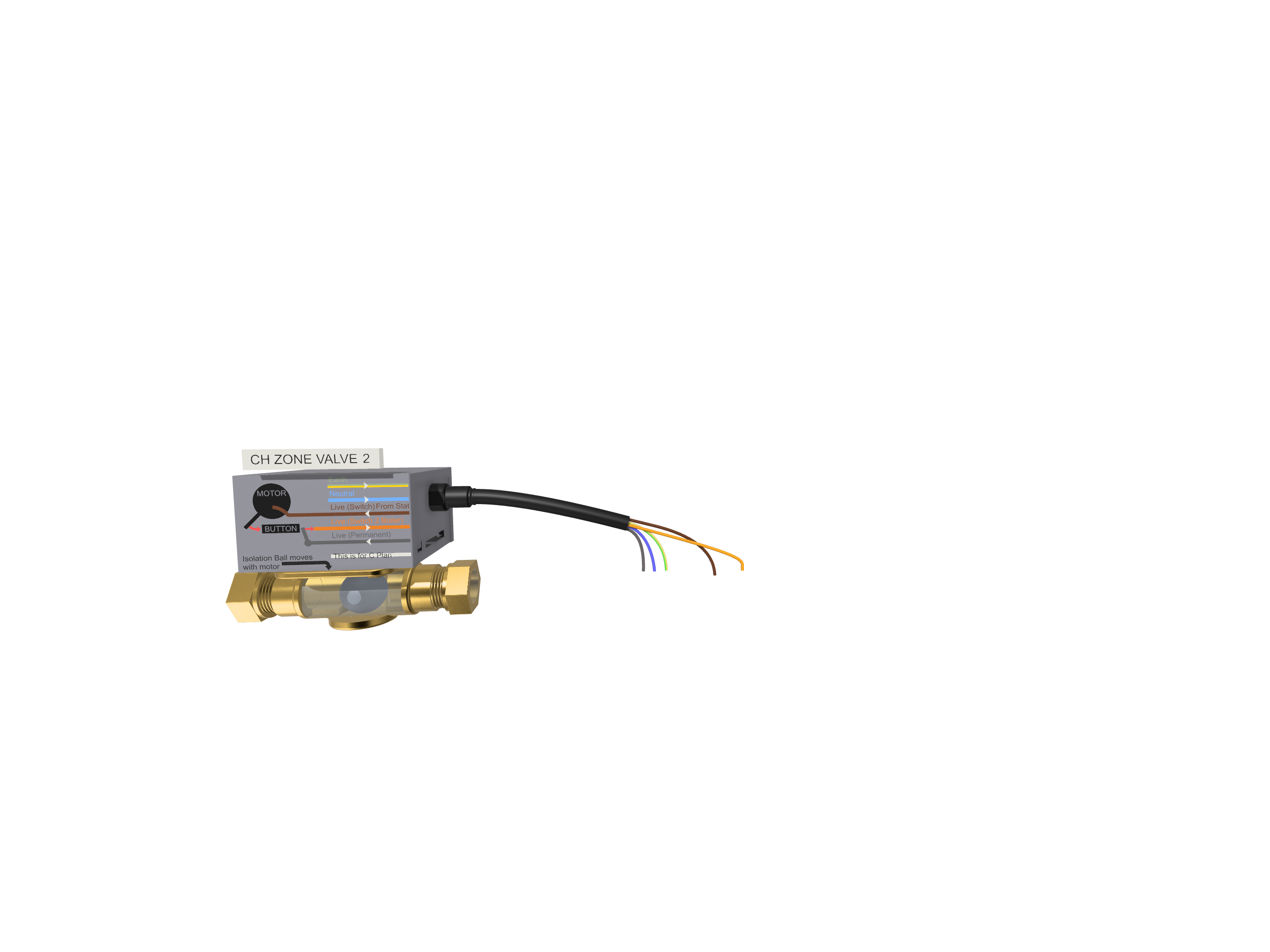
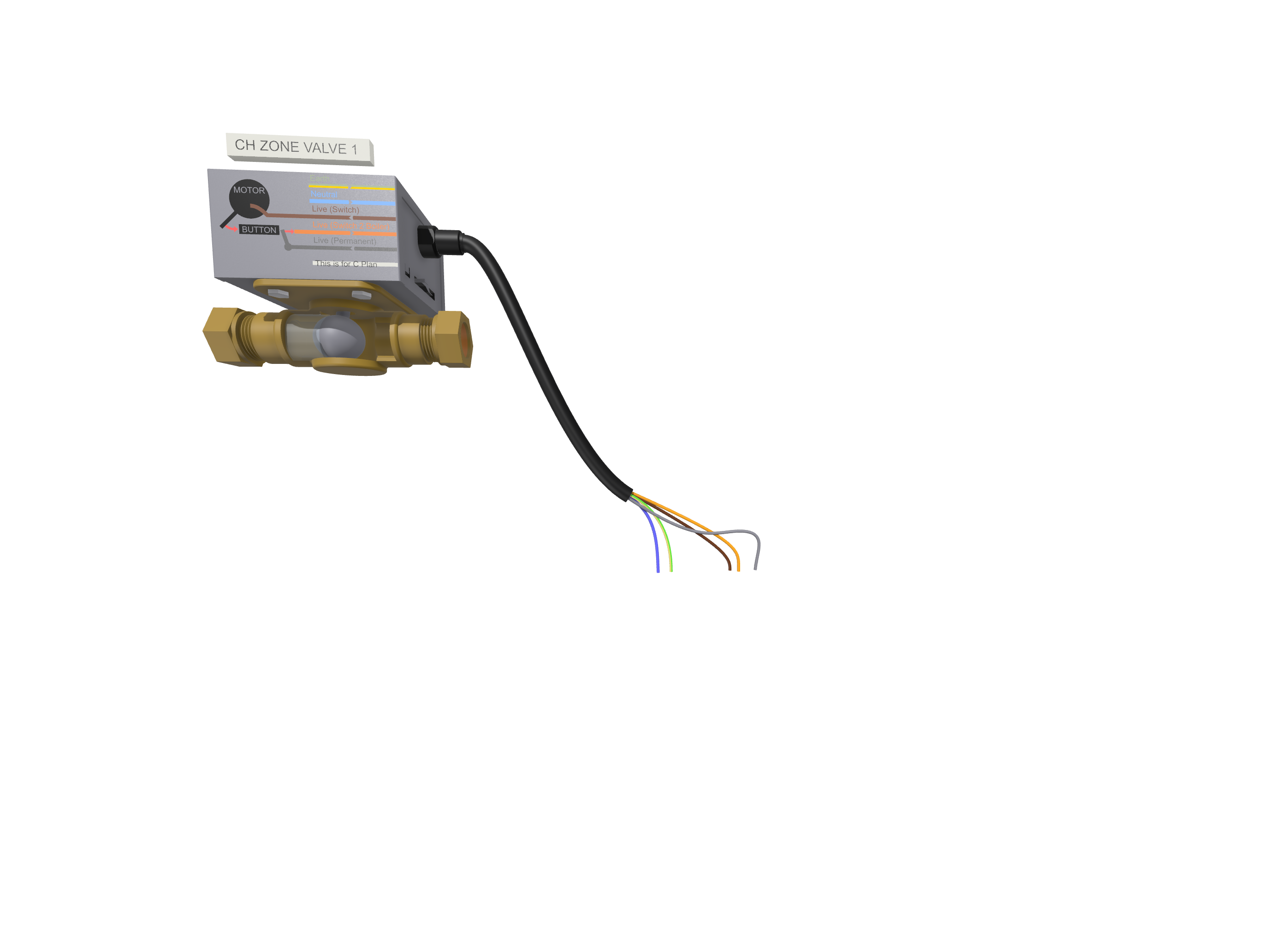
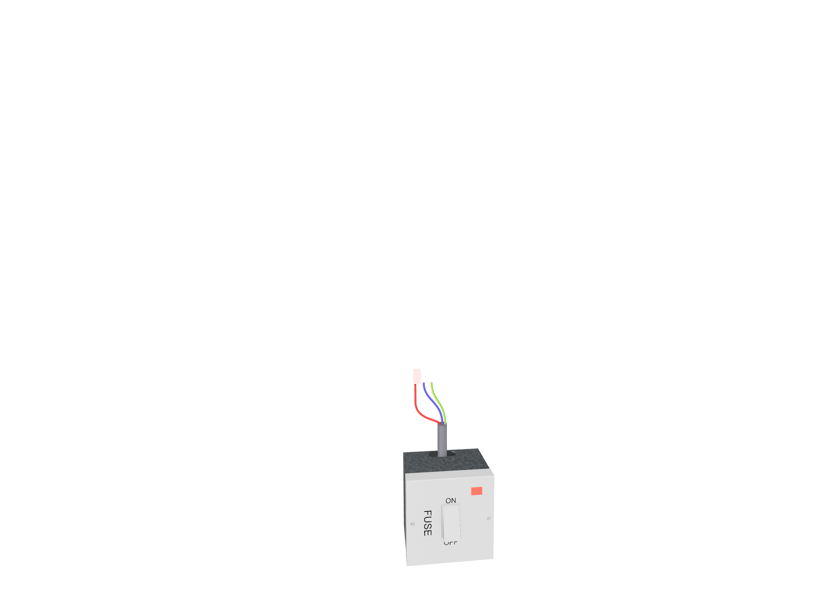
In a 240V zoned heating system, the grey wire of the zone valve is connected to terminal 1, where the switch spur is also connected. This setup ensures a permanent live supply to the diverter valve, allowing it to receive power when the system requires heating. The benefit of this method is that it enables immediate response when the thermostat calls for heat, ensuring minimal delay and efficient heating control.
Why Use Terminal 1 for 230V Supply?
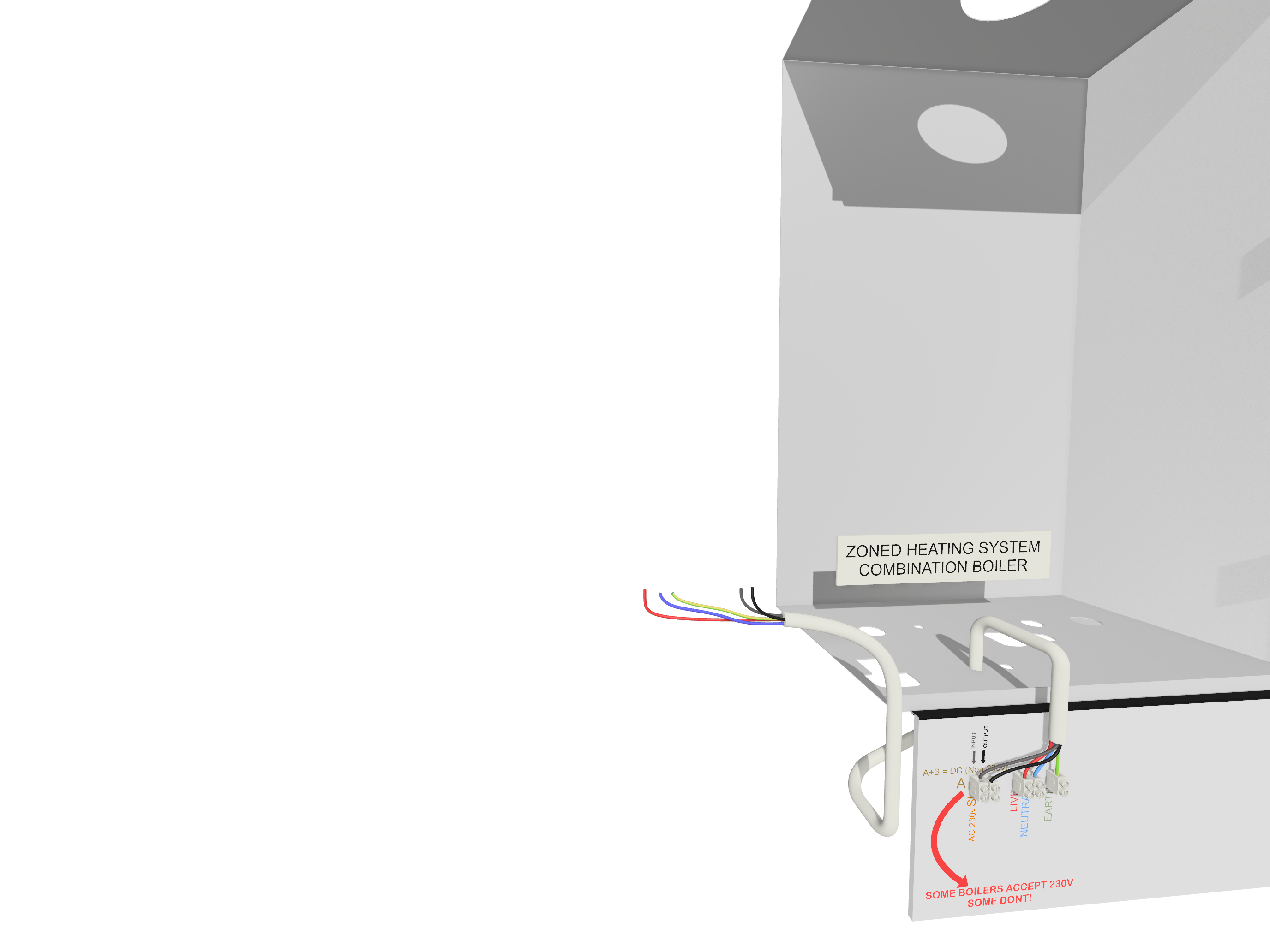
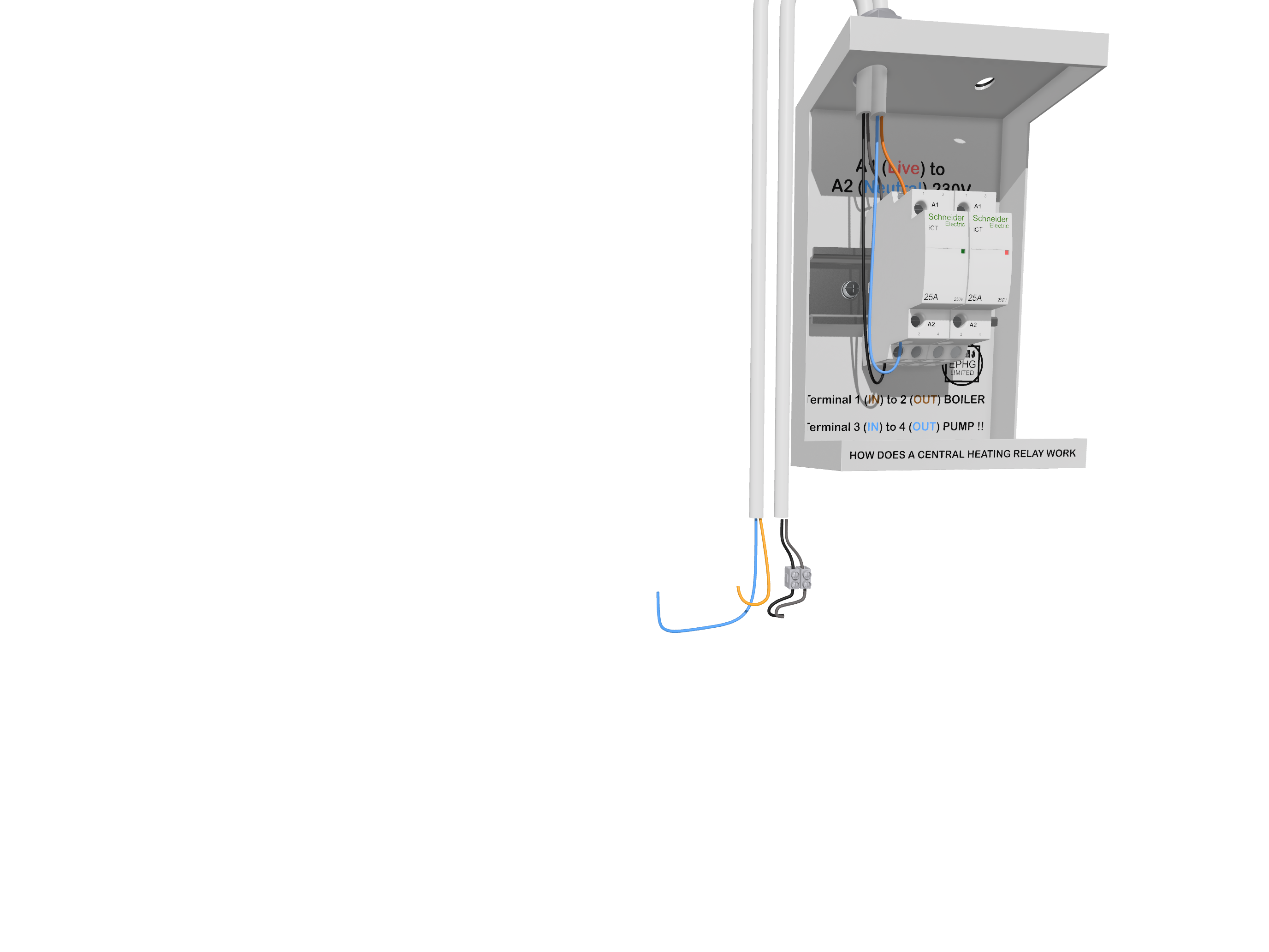
The decision to use terminal 1 for the 230V supply is primarily to create a centralized and reliable power source. By doing so, the heating system can avoid potential power interruptions and provide a fail-safe mechanism, ensuring the heating demand is met without interruptions. This method is commonly used in combi boilers and system boilers where a direct 230V supply is required to operate the zone valves efficiently.
Key Components of a 240V Zoned Valve System
The essential components of a 240V zoned heating system include:
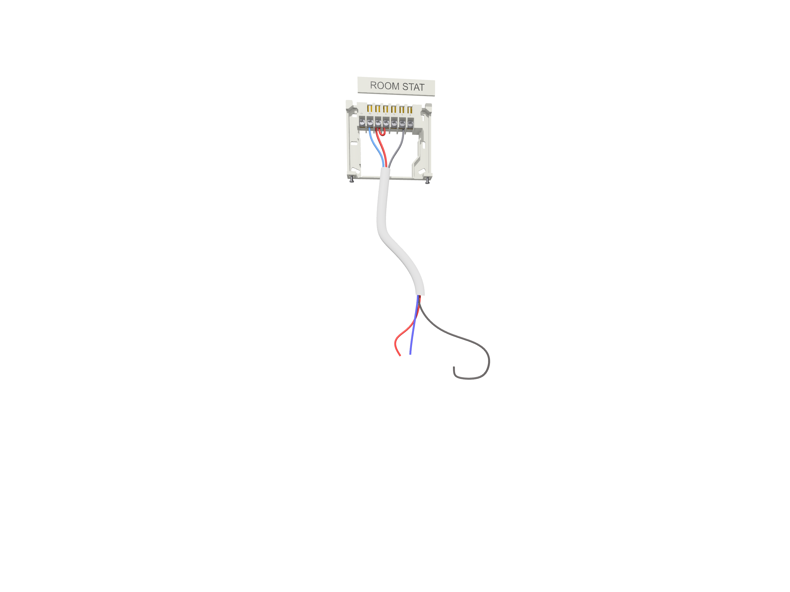
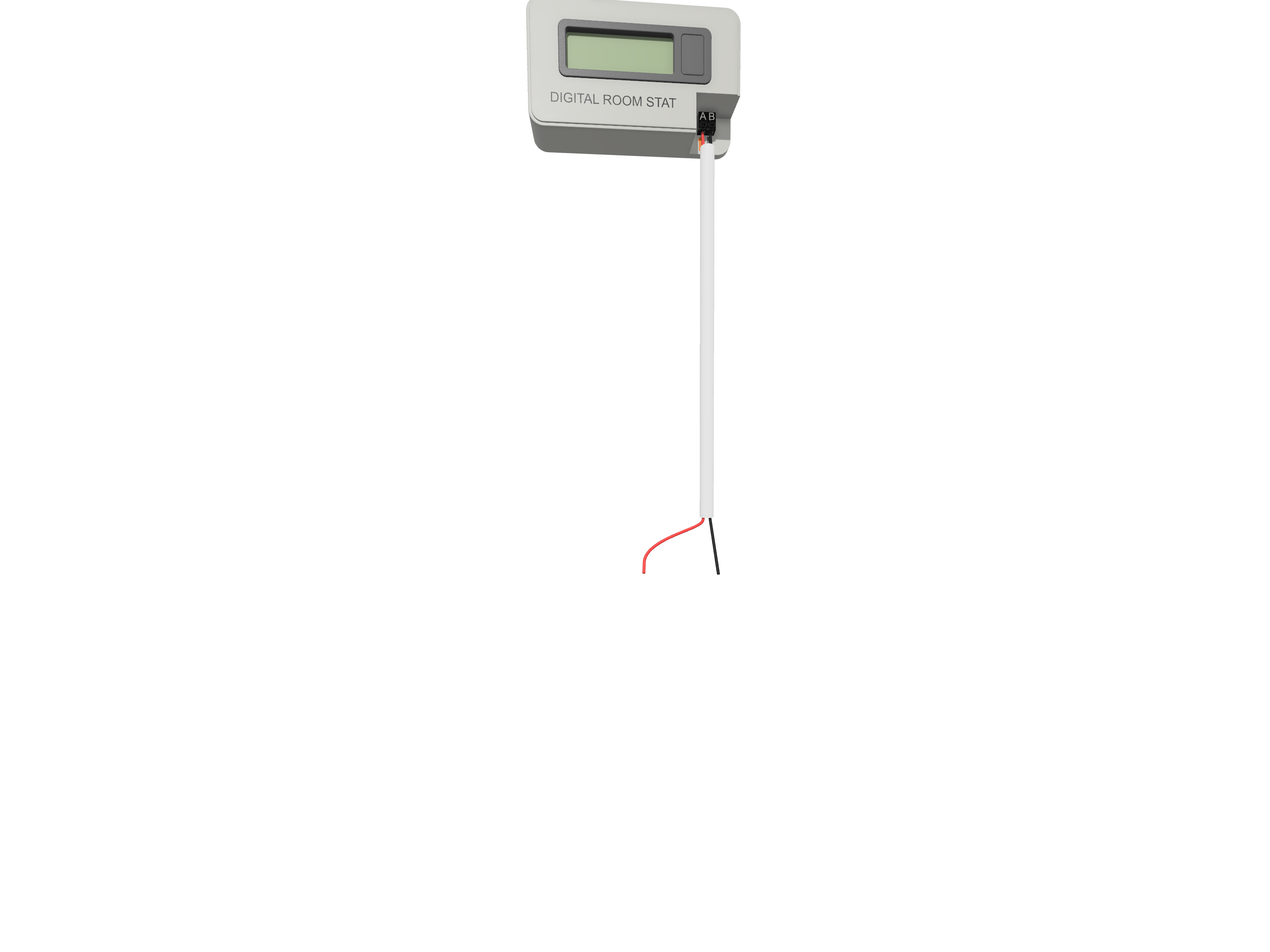
- Thermostats: Control the temperature of each heating zone.
- Motorized Zone Valves: 240V valves regulate hot water distribution.
- Boiler: Generates hot water to supply the heating system.
- Wiring Center: Provides a central hub for all electrical connections.
- Pump: Circulates hot water through the heating system.
Step-by-Step 240V Wiring Guide
Follow these steps to wire a 240V zoned valve system correctly:
- Step 1: Identify the correct terminals on the valve (live, neutral, earth, switch live).
- Step 2: Connect the thermostat to the appropriate wiring terminal.
- Step 3: Link the valve to the boiler to trigger heating when required.
- Step 4: Wire the pump to the system for proper circulation.
- Step 5: Perform system tests to ensure all zones respond correctly.
Common Wiring Configurations
There are several ways to wire a 240V zoned heating system, including:
- Standard S-Plan: Individual zone control with separate valves for heating and hot water.
- Y-Plan: Single 3-port valve to manage both heating and hot water.
- S-Plan Plus: Multiple zones controlled independently via separate valves.
Benefits of a 240V Zoned Valve System
Choosing a 240V zoned heating system offers numerous benefits, such as:
- Improved Comfort: Independent control over heating zones.
- Energy Efficiency: Reduces energy consumption by heating only necessary areas.
- Compatibility: Works seamlessly with most standard boilers and thermostats.
Troubleshooting 240V Zoned Valve Systems
If you encounter issues with your 240V system, consider the following troubleshooting tips:
- Zone Not Heating: Check thermostat settings and wiring connections.
- Valve Stuck: Ensure the actuator motor is functioning correctly.
- No Power: Verify fuse integrity and electrical supply.
Related Zoned Valve Wiring Diagrams
Explore other related wiring diagrams for different voltage setups:
- 24V Zoned Valve Wiring Diagram – Learn about the 24V system where the zone valve’s grey wire gets its controlled 24V directly from the boiler.
- 24V/240V Combined Zoned Valve Wiring Diagram – Discover how to integrate both 24V and 240V systems using relays for better electrical isolation.
Conclusion
A properly wired 240V zoned valve system ensures efficient heating management in homes and commercial buildings. By following the correct wiring methods and troubleshooting tips, you can optimize your heating system for better performance and reliability. For an overview of various heating wiring plans, visit our Central Heating Wiring Plans page.