Central Heating Activation Sequence in an Advanced Logic Combi Boiler
The image container is fully interactive, allowing you to visualize the central heating activation process step by step. Don't forget to check our Combi Boiler Hot Water Activation Guide for a detailed breakdown of how the hot water system operates.


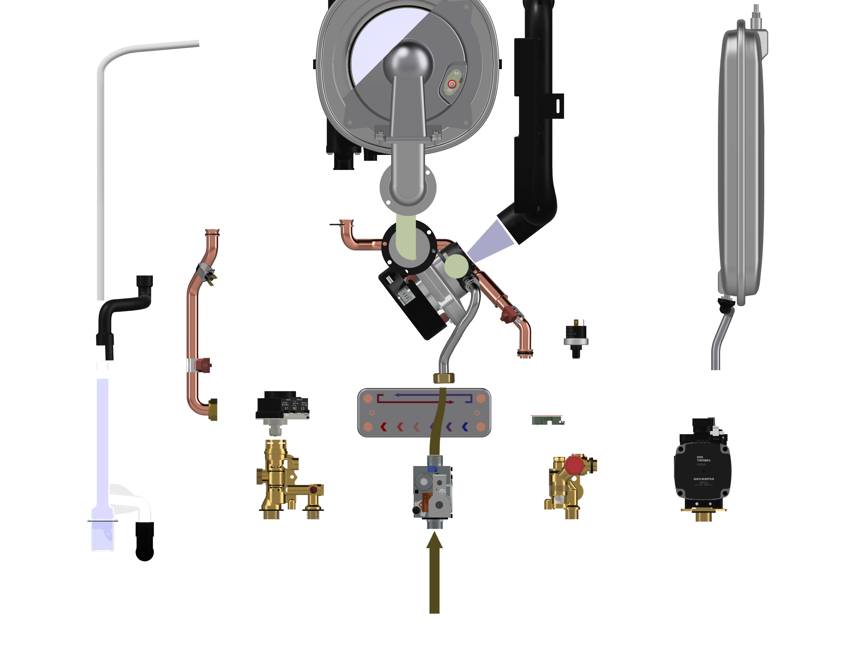


Understanding Central Heating Activation in Combi Boilers
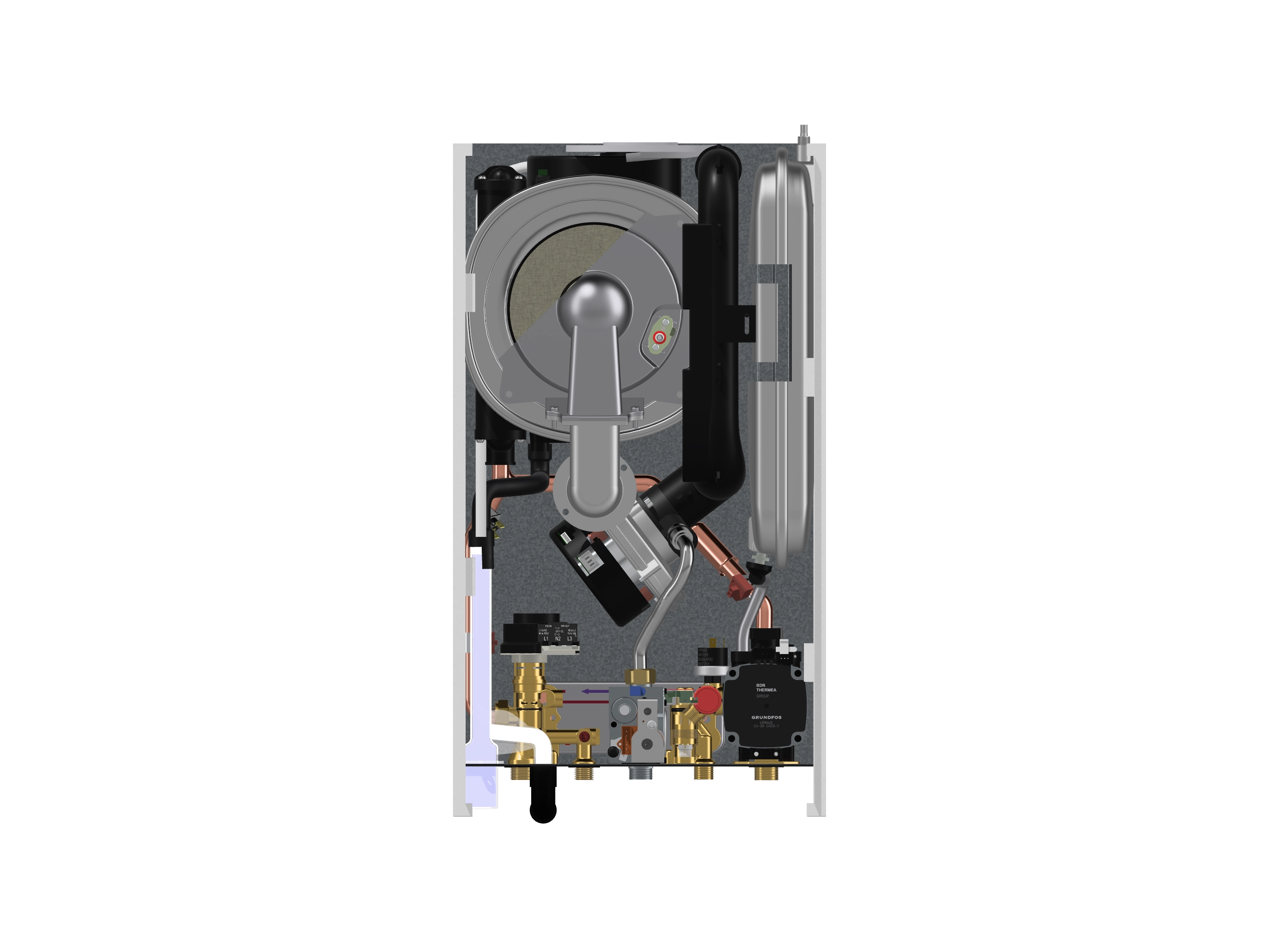
Combi boilers provide both hot water and central heating on demand. Unlike conventional heating systems, which use external hot water storage, a combi boiler operates by directly heating water as it is needed. This guide will walk you through the step-by-step activation sequence, explaining the electrical and mechanical operations, voltage readings, and fault diagnostics for a combi boiler in central heating mode.

Step 1: Standby Mode (No Heating Demand)
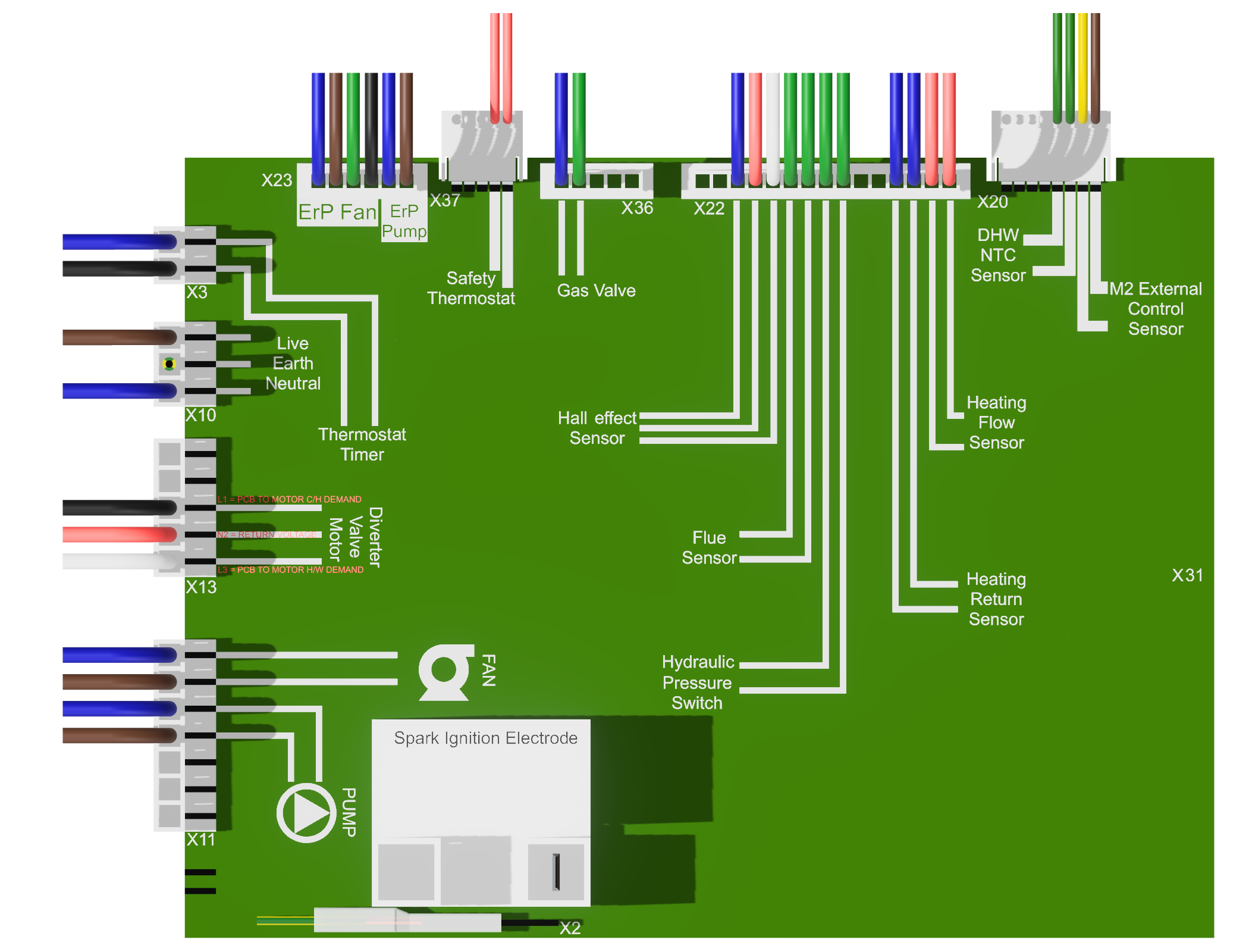
When the boiler is on but no heat demand is present, the PCB (Printed Circuit Board) remains powered and continuously monitors the system. The PCB checks for signals from the room thermostat, programmer, and diverter valve to determine when to activate heating.
Voltage Readings in Standby Mode:
- Main Live (L) to Neutral (N): 230V AC
- PCB Power Circuit: 5V DC for control logic, 230V AC for main operation
- Room Thermostat Output (Inactive): 0V
- Programmer Switched Live: 0V
- Diverter Valve Position Feedback: 0V
- Pump Activation Signal: 0V
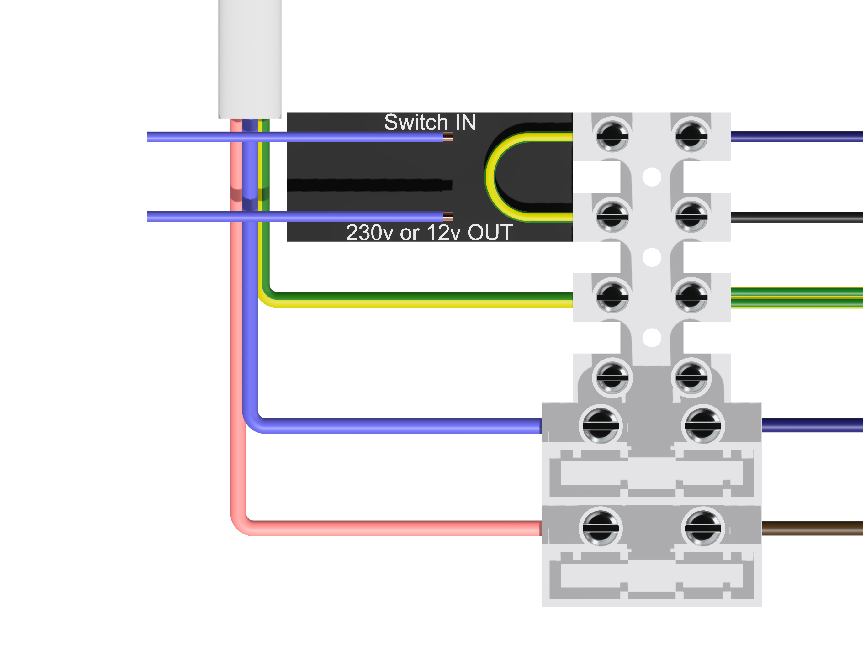
Step 2: Thermostat Activation & Programmer Call for Heat
When the room thermostat detects a drop in temperature, it completes the 230V switched live circuit, sending a demand signal to the boiler's PCB.
Expected Voltage Readings:
- Room Thermostat Output: 230V AC (when demand is active)
- Programmer Live to PCB: 230V AC
Step 3: Diverter Valve Activation
The PCB responds by activating the diverter valve motor, shifting it into central heating mode. This valve determines whether heated water is sent to the radiators or the hot water circuit.
Voltage Readings:
- PCB L1 Output to Diverter Motor: 230V AC
- Diverter Valve Microswitch Feedback: 230V AC (verifying valve movement)
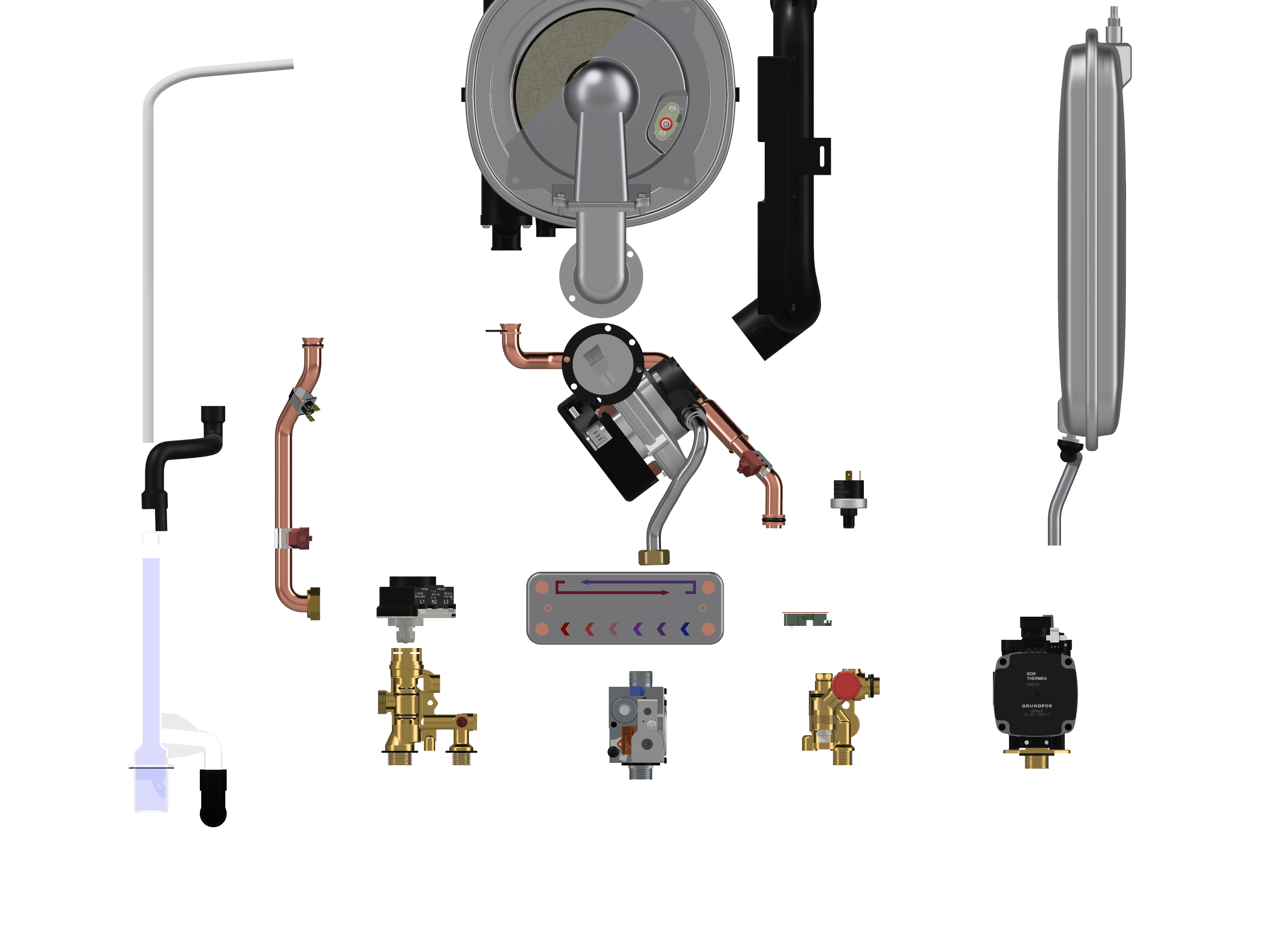
Step 4: Fan & Pump Activation
The boiler’s fan and circulating pump must be operational before ignition can proceed. The fan ensures safe combustion, while the pump circulates water through the heat exchanger and radiators.
Voltage Checks:
- Fan Live (ERP Fan): 230V AC
- Pump Live: 230V AC
- Air Pressure Switch Feedback: 5V DC (confirming airflow)
Step 5: Gas Valve & Ignition Activation
With airflow confirmed, the PCB signals the gas valve to open and releases gas into the burner. The ignition electrode generates a spark to ignite the gas, producing a flame that heats the water.
Voltage Readings:
- Gas Valve Live: 230V AC
- Ignition Electrode: 5V – 15V DC pulse
- Flame Sensor Feedback: 5V DC (indicating a stable flame)
Step 6: Radiator Heating & Water Circulation
Once the flame is stable, the boiler begins modulating its output based on the flow and return temperature sensors. Heated water is circulated to radiators, providing warmth.
Final Voltage Readings:
- NTC Sensor (Flow Temperature): 5V DC
- Pump Live: 230V AC
- Return Sensor (Monitoring Heat Exchange): 5V DC
Common Faults & Troubleshooting
1. No Central Heating?
Check if 230V AC is reaching the thermostat output and the diverter valve moto.
- If there’s no 230V at the thermostat, check power supply and wiring.
- If the diverter valve is stuck, manually shift it to verify movement.
- If no voltage is present at the L1 diverter terminal, the PCB may be faulty.
2. Diverter Valve Stuck?
The diverter valve might be blocked or its motor may have failed.
- Check 230V AC at L1 output.
- If voltage is present but the valve doesn’t shift, the valve motor is likely faulty.
- If no voltage is detected, inspect the PCB relay controlling L1 output.
3. No Ignition?
If the boiler fails to ignite, follow these steps:
- Ensure 5V – 15V DC pulse at the ignition electrode.
- Check if the gas valve receives 230V AC during ignition.
- Verify the flame sensor feedback (5V DC) is detected by the PCB.
4. No Circulation?
If the pump is not running, check:
- Pump voltage (230V AC) at the terminals.
- Airlocks or sludge blocking circulation.
- Pump capacitor failure or impeller blockage.
Conclusion
By following this detailed wiring sequence, voltage checks, and troubleshooting guide, heating engineers can diagnose and fix central heating activation issues efficiently. Understanding the electrical and mechanical sequence allows for quick and accurate fault-finding.
Important Disclaimer
The information provided in this guide is for educational purposes only and should not be used as a substitute for professional training or certification. Electrical and gas-related work must comply with UK safety regulations, and incorrect handling can pose serious risks, including electrical shock, gas leaks, and boiler malfunctions. Always consult a qualified heating engineer or Gas Safe registered professional if you are unsure or lack the required expertise.
Further Reading
A combi boiler not only heats your home but also provides instant hot water on demand. To learn how the hot water activation sequence works, including how the plate heat exchanger, flow sensors, and diverter valve function, visit our dedicated guide on Combi Boiler Hot Water Activation.