Understanding Gas Valves in Combi Boilers
The gas valve is one of the most crucial components in a combination boiler, controlling the flow of gas to the burner. This guide explains how gas valves work, common issues they face, how to diagnose faults, and the best actions to take for repair.
Understanding the 4-Pin Gas Valve in a Baxi Boiler
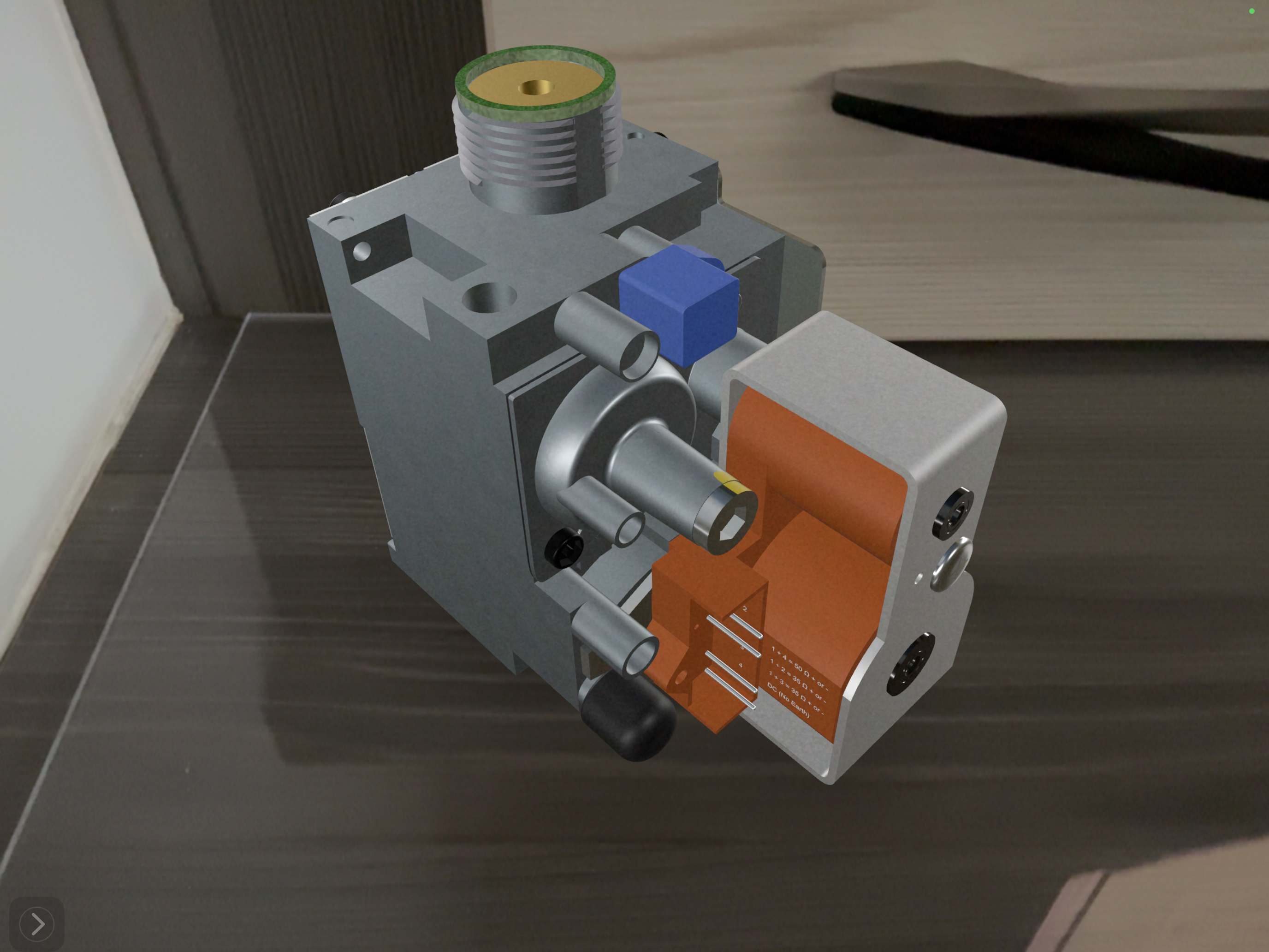
In the image to the right, you will see a complete gas valve drawing designed for a Baxi boiler, which features four electrical pins. These pins play a crucial role in controlling the operation of the gas valve and ensuring proper gas flow to the burner.
Breakdown of the Four Pins
Two Outter Control Pins (Connected to the Wiring Harness & PCB)
- These two pins are directly connected to the boiler’s wiring harness, which links back to the Printed Circuit Board (PCB).
- When the boiler calls for heat, the PCB sends an electrical signal (230V AC during ignition) to these pins, which in turn activate the solenoid and allow gas to flow.
- The PCB also modulates the gas valve operation by sending a varying DC voltage (typically 0-20V DC), which adjusts the gas flow based on demand.
Two Solenoid Pins (Used for Resistance Testing)
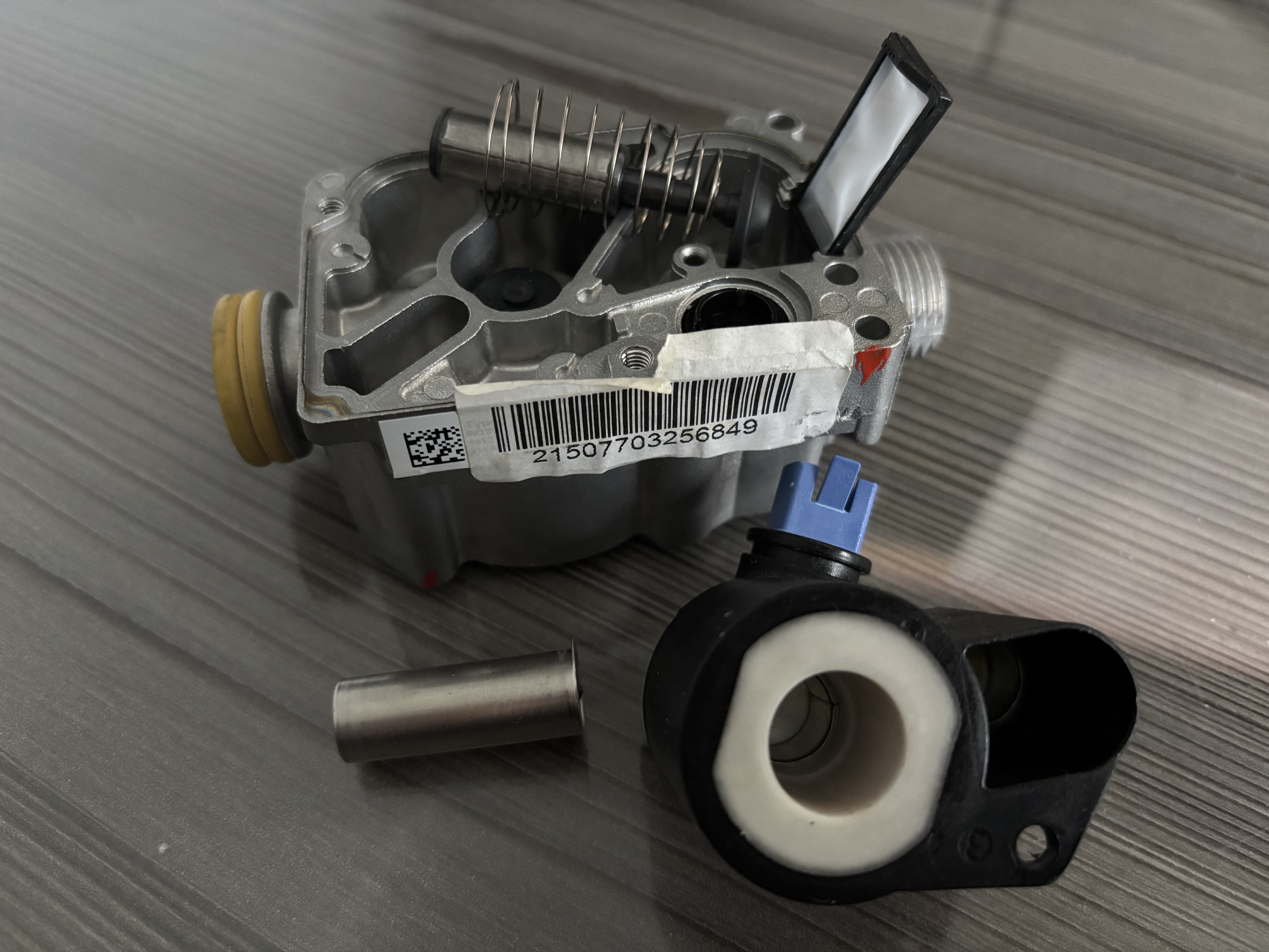
- The remaining two pins belong to the gas valve solenoid coil, which is responsible for the mechanical operation of the valve.
- These pins do not connect directly to the PCB but are instead part of the electromagnetic coil inside the gas valve.
- By energizing this coil, the solenoid opens the valve, allowing gas to pass through and ignite the burner.
Testing the Gas Valve Pins
To ensure the gas valve is functioning correctly, you can perform two key electrical tests:
1. Checking Voltage to the Control Pins
- Set your multimeter to AC voltage and measure across the two control pins.
- When the boiler calls for heat, you should see approximately 230V AC.
- If no voltage is present, check for wiring faults between the PCB and gas valve.
2. Measuring Solenoid Resistance
- Set your multimeter to the Ohms (Ω) setting.
- Place the probes across the two solenoid pins and check the resistance.
- Expected readings:
- Most Baxi gas valve solenoids: 50Ω - 200Ω
- Common range: 80Ω - 150Ω
- If resistance is too low (<20Ω): The coil may be shorted.
- If resistance is too high (>200Ω or "OL" reading): The coil may be open or faulty.

How Gas Valves Work in Combi Boilers
The gas valve regulates the flow of gas to the burner, ensuring that the correct amount of fuel is supplied for ignition and combustion. Modern gas valves are electronically controlled by the boiler's Printed Circuit Board (PCB) and modulate the gas flow based on heating demand.
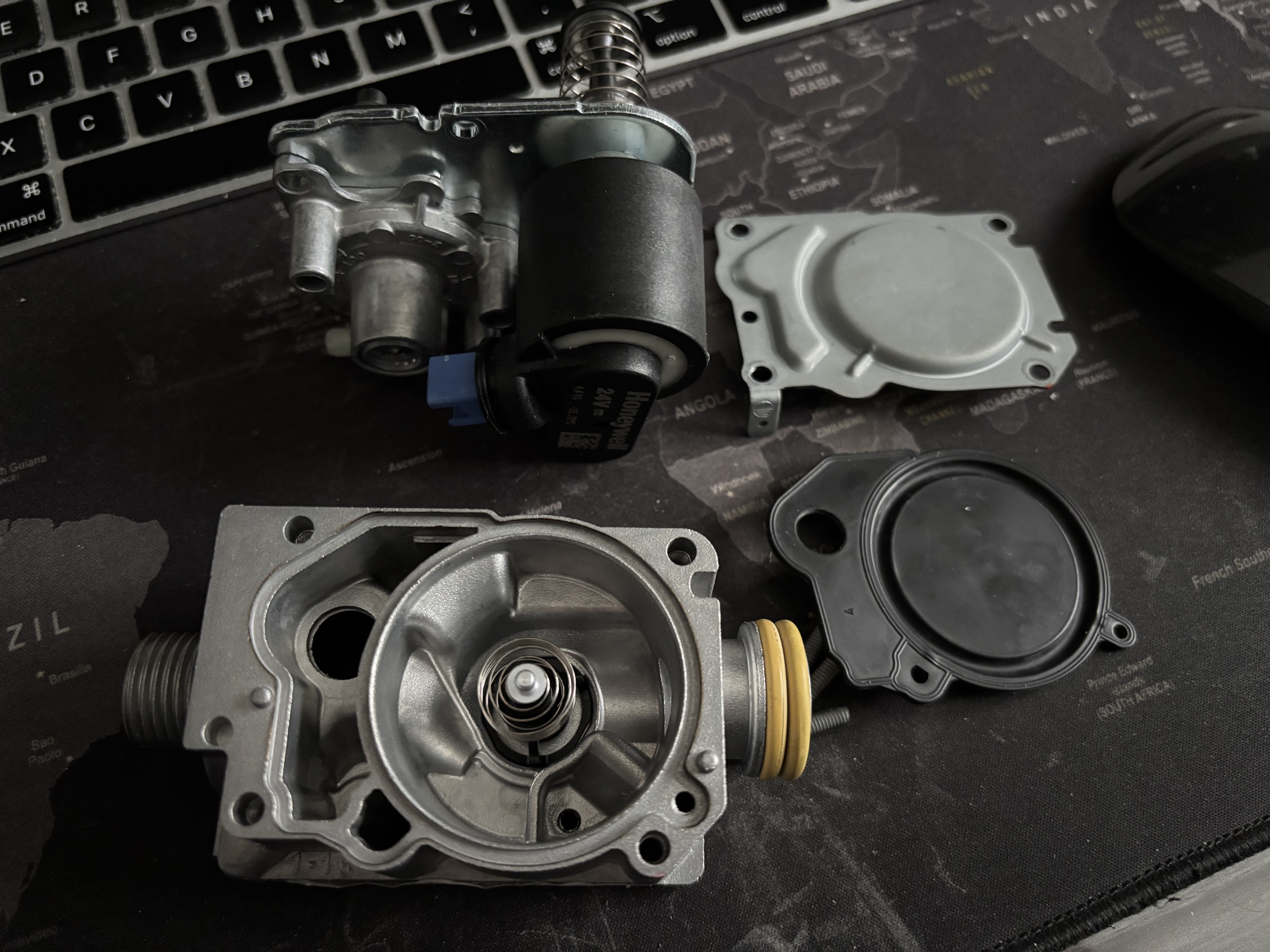
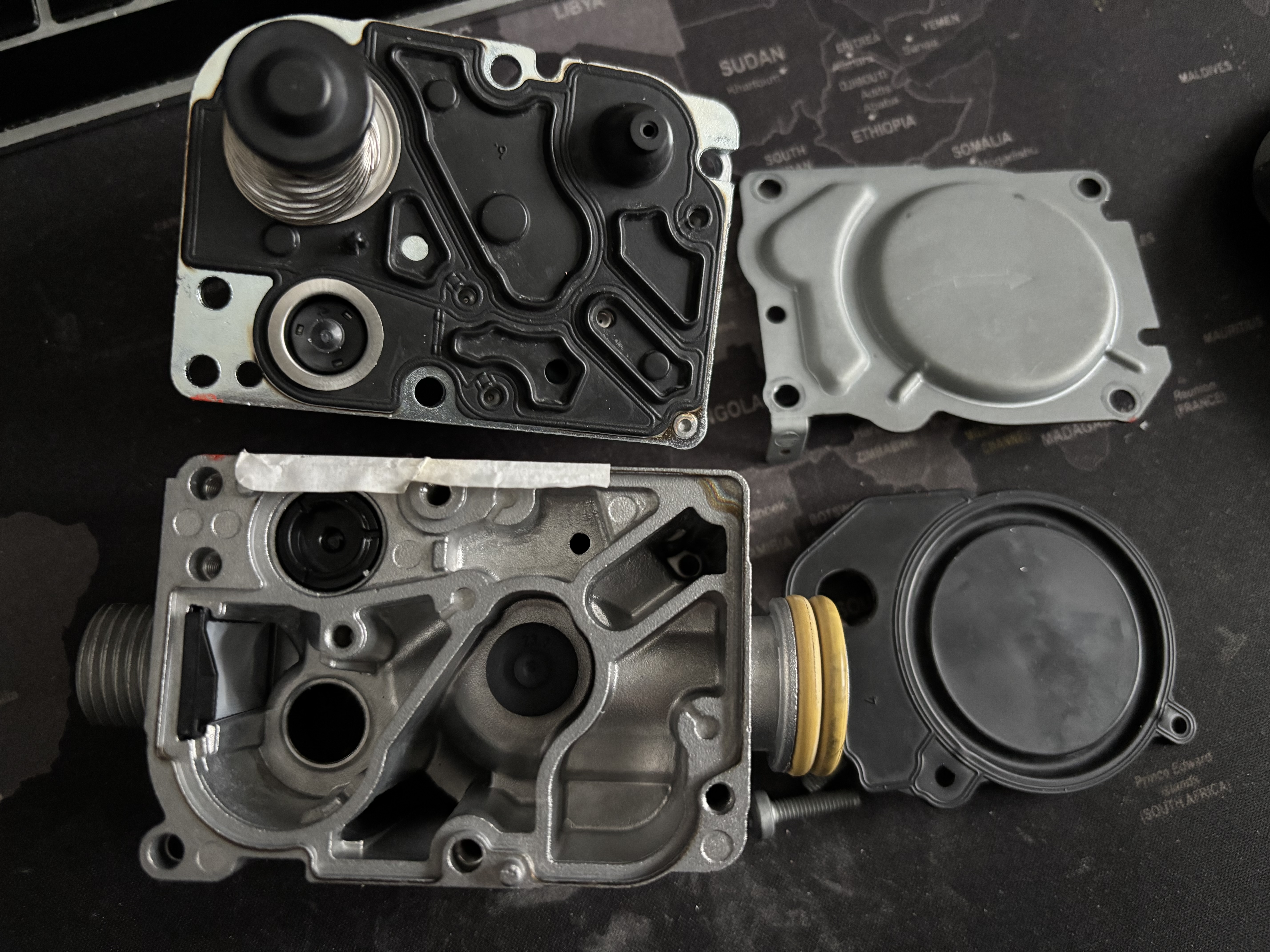
Main Components of a Gas Valve
- Solenoid Coils: Electrically operated to open and close gas flow.
- Modulation Control: Adjusts gas supply according to demand.
- Safety Shut-Off Valve: Closes gas supply in case of a fault.
- Pressure Adjustment Screws: Allow fine-tuning of gas pressure.
Gas Pressures and Voltage Requirements
Gas valves operate with specific pressures and electrical signals to ensure safe and efficient combustion. Here are the key specifications:
- Gas Inlet Pressure: Typically 18-25 mbar for natural gas (NG) and 37-50 mbar for LPG.
- Burner Pressure: Generally 7-13 mbar for NG and 20-37 mbar for LPG, depending on manufacturer settings.
- Voltage Supply: 230V AC during ignition phase.
- Modulation Voltage: 0-20V DC signal from the PCB for flame control.

Checking the Harness
The wiring harness plays a crucial role in delivering electrical signals between the gas valve and the boiler’s PCB. A faulty or loose harness connection can result in inconsistent voltage readings or complete failure of the gas valve to operate. To check the harness, inspect all connectors for signs of corrosion, damage, or loose fittings. Using a multimeter, measure the voltage at the gas valve terminals while the boiler attempts ignition; it should read approximately 230V AC. Additionally, check for continuity along the harness wires to ensure no internal breaks or high resistance that could disrupt the electrical flow. Use a multimeter set to ohms to measure the resistance across the harness wiring. A healthy harness should show low resistance, typically in the range of 0Ω to 1Ω. Some engineers prefer an intermediate value rather than an absolute zero reading, as a perfectly zero reading might indicate shorted wiring rather than a fully functional connection. If the reading is significantly higher, it may indicate a break or poor connection within the wiring. If any anomalies are found, secure all connections or replace the faulty section of the harness.
Typical Resistance Values for Gas Valve Solenoids
When testing a gas valve solenoid, resistance measurements can indicate whether the component is functioning correctly. Expected ranges include:
- Most modern gas valve solenoids: 50Ω - 200Ω
- Common range: 80Ω - 150Ω
- If the resistance is too low (<20Ω): The coil may be shorted.
- If the resistance is too high (>200Ω or "OL" reading): The coil may be open or faulty.

Additional Checks for Gas Valve Diagnosis
- Compare with Manufacturer Specs: Check the boiler manual for the correct solenoid resistance range.
- Check for Continuity: If the meter shows "OL" (open loop), the coil is likely broken.
- Voltage Test: Ensure the valve is receiving the expected 230V AC during ignition and that the modulation voltage is within the 0-20V DC range.
- Functional Test: If the valve doesn’t open even with correct voltage, it may be stuck or faulty.
Common Faults in Gas Valves
Gas valves can fail due to electrical faults, blockages, or wear and tear. Here are some typical issues:
- Gas Valve Sticking: The valve may get stuck open or closed, preventing proper gas flow.
- Solenoid Failure: A failed solenoid prevents the valve from opening.
- Incorrect Gas Pressure: Too high or too low pressure affects combustion.
- PCB Signal Failure: If the PCB doesn’t send the correct signal, the valve won’t open.
Diagnosing Gas Valve Faults
When diagnosing a faulty gas valve, follow these steps:
Step 1: Check for Error Codes
Most modern boilers display an error code indicating a gas valve fault.
Step 2: Test the Gas Supply
Ensure the gas meter is supplying gas correctly and check for external shut-off valves.
Step 3: Measure Voltage to the Gas Valve
Use a multimeter to check for 230V AC at the gas valve terminals when ignition is attempted.
Additionally, check the modulation voltage from the PCB, which should vary between 0-20V DC.
Step 4: Check Gas Pressure
Use a digital manometer to check gas inlet and burner pressure:
- Compare measured values with manufacturer specifications.
- If pressure is too low, check the gas meter and regulator.
- If pressure is too high, adjust using the valve’s pressure adjustment screws.
Step 5: Inspect the Solenoids
Test solenoid resistance using a multimeter; if readings are out of range, the solenoid is faulty.
Best Actions for Repair
If a gas valve fault is confirmed, the following actions may be required:
- Reset the boiler and attempt ignition.
- Check wiring connections between the PCB and gas valve.
- Replace faulty solenoids if applicable.
- Replace the entire gas valve if it is beyond repair.
Safety Considerations
Working on gas appliances requires Gas Safe registration. Always perform gas tightness tests after any work on the gas valve and ensure combustion is safe using a flue gas analyzer.
Conclusion
Gas valves play a critical role in a combi boiler's operation. Understanding how they work, diagnosing faults correctly, and taking appropriate actions ensures safe and efficient boiler performance.